
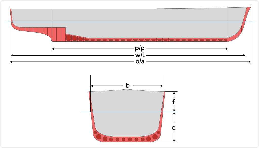
Graphical representation of the dimensions used to describe a ship. Dimension “b“ is the beam
The beam of a ship is its width at the widest point. Generally speaking, the wider the beam of a ship (or boat), the more initial stability it has, at expense of reserve stability in the event of a capsize, where more energy is required to right the vessel from its inverted position. Typical length-to-beam ratios for small sailboats are from 2:1 (dinghies to trailerable sailboats around 20 ft/6 m) to 5:1 (racing sailboats over 30 ft/10 m). Large ships have widely varying beam ratios, some as large as 20:1. Rowing shells designed for flatwater racing may have length to beam ratios as high as 30:1 [1], while a coracle has a ratio of almost 1:1 – it is nearly circular.
The beam of many monohulls can be calculated using the following formula:
- Beam = LOA2 / 3 + 1
LOA is Length Overall.
All units are in feet.
Some examples
– For a standard 27′ (8.23m) yacht: the cube root of 27 is 3, 3 squared is 9 plus 1 = 10. The beam of many 27′ monohulls is 10′ (3.05m).
– For a Volvo Open 70 yacht: 70.5 to the power of 2/3 = 17 plus 1 = 18. The beam is often around 18′ (5.5m).
– For a 741′ (226m) long ship: the cube root is 9, and 9 squared is 81, plus 1. The beam will usually be around 82′ (25m) e.g. Seawaymax.
_oOo_
Draft (hull)
The draft (or draught) of a ship’s hull is the vertical distance between the waterline and the bottom of the hull (keel), with the thickness of the hull included; in the case of not being included the draft outline would be obtained. Draft determines the minimum depth of water a ship or boat can safely navigate. The draft can also be used to determine the weight of the cargo on board by calculating the total displacement of water and then using Archimedes’ principle. A table made by the shipyard shows the water displacement for each draft. The density of the water (salt or fresh) and the content of the ship’s bunkers has to be taken into account. The closely related term “trim” is defined as the difference between the forward and after drafts.
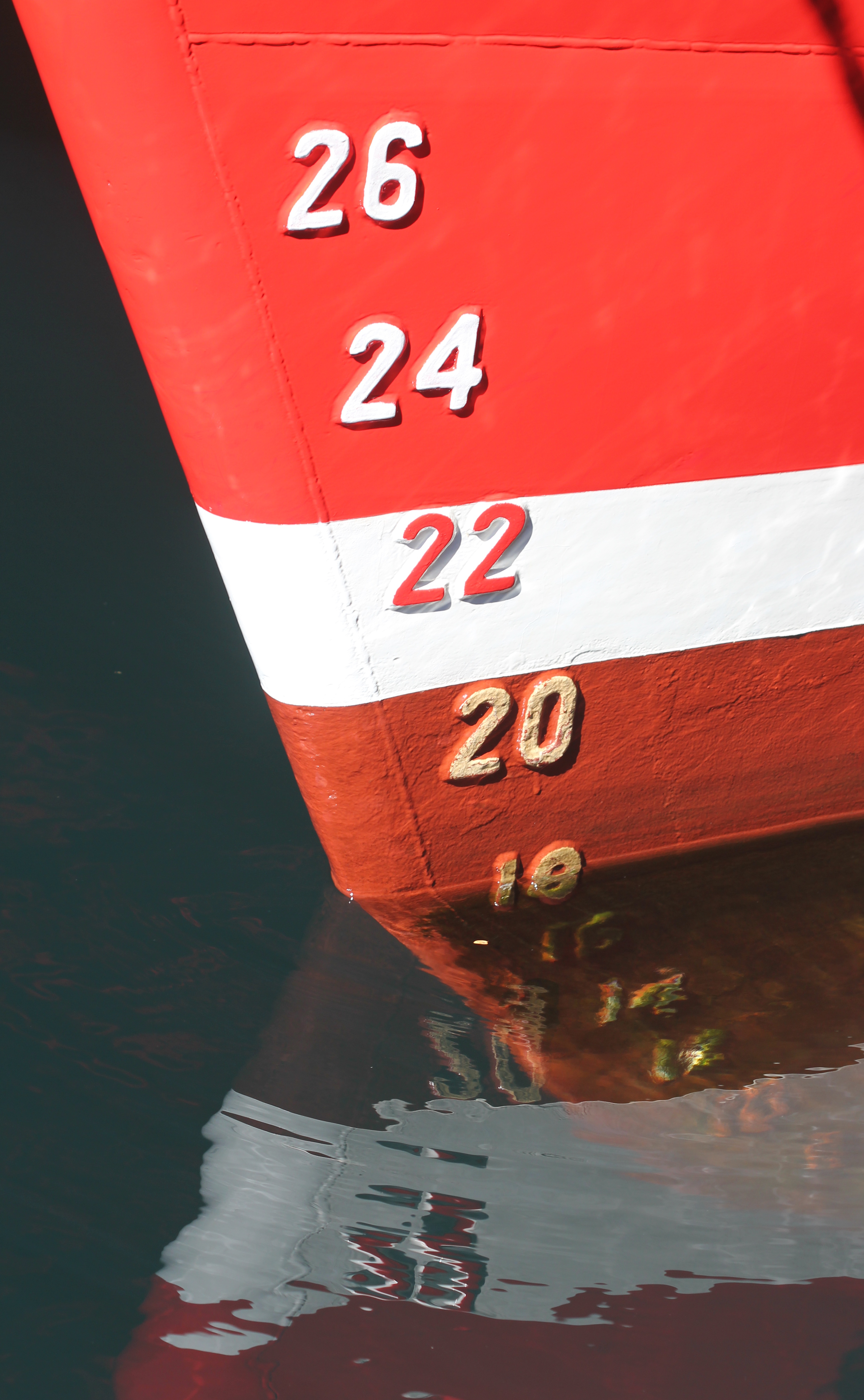
Draft marks on a ship’s bow
Drafts of a ship
- The draft aft (stern) is measured in the perpendicular of the stern.
- The draft forward (bow) is measured in the perpendicular of the bow.
- The mean draft is obtained by calculating from the averaging of the stern and bow drafts, with correction for water level variation and value of the position of F with respect to the average perpendicular.
[edit] Variations of the draft
The draft of a ship can be affected by multiple factors, not considering the rise and fall of the ship by displacement:
- Draft variation by list
- Draft variation by water level change[clarification needed]
- Allowance of fresh water draft variation by passage from fresh to sea water or vice versa
- Heat variation in navigating shallow waters

Metric bow scale
*

English system in Roman numeration of the bow scale
***
Draft scale
The drafts are measured with a “banded” scale, from bow and to stern, and for some ships, the average perpendicular measurement is also used. The scale may use traditional English units or metric units. If the English system is used, the bottom of each marking is the draft in feet and markings are 6 inches high. In metric marking schemes, the bottom of each draft mark is the draft in decimeters and each mark is one decimeter high.
Graphical representation of the dimensions used to describe a ship. Dimension “d“ is the draft
***
The implications of draft
Large ships
Larger ships try to maintain an average water draft when they are light (without cargo), in order to make a better sea crossing and reduce the effects of the wind (high centre of velic force). In order to achieve this they use sailing ballasts to stabilize the ship, following the unloading of cargo.
The water draft of a large ship has little direct link with its stability, the latter depends solely on the respective positions of the metacenter of the hull and the centre of gravity. It is also true however, that a “light” ship has quite high stability which can lead to implying too much rolling of the ship (due to memory). A fully laden ship (with a large draft) can have a strong or on the contrary, a weak stability, depending upon the manner by which the ship is loaded (height of the centre of gravity).
The draft of ships can be increased when the ship is in motion, a phenomenon known as squat (nautical term for the hydrodynamic effect of lower pressure pulling the ship down as it moves).
Draft is a significant factor limiting navigable waterways, especially for large vessels. Of course this includes many shallow coastal waters and reefs, but also some major shipping lanes. Panamax class ships—the largest ships able to transit the Panama Canal—do have a draft limit (and an “air draft” limit for passing under bridges) but are usually limited by beam, or sometimes length overall, for fitting into locks. However in the much wider Suez Canal, the limiting factor for Suezmax ships is draft. Some supertankers are able to transit the Suez Canal when unladen or partially laden, but not when fully laden.
Canals are not the only draft-limited shipping lanes. A Malaccamax ship has the deepest draft able to transit the very busy but relatively shallow Strait of Malacca. There are only a few ships of this size.
***
Pleasure boats
A small draft allows pleasure boats to navigate through shallower water. This makes it possible for these boats to access smaller ports, to travel along rivers and even to ‘beach’ the boat.
A large draft ensures a good level of stability in strong wind, as the centre of gravity is lower (ballast over the keel of the boat). For example: Ballasts placed very low in the keel of a boat such as a dragon boat with a draft of 1.20 m for a length of 8.90 m.
A boat like a catamaran can mitigate the problem by retrieving good stability in a small draft, but the width of the boat increases.
***
Submarines
For submarines, which can submerge to different depths at sea, a term called keel depth is used, specifying the current distance from the water surface to the bottom of the submarine’s keel. It is used in navigation to avoid underwater obstacles and hitting the ocean bottom, and as a standard point on the submarine for depth measurements.
Submarines usually also have a specified draft used while operating on the surface, for navigating in harbors and at docks.
_oOo_
Keel
In boats and ships, keel can refer to either of two parts: a structural element, or a hydrodynamic element. These parts overlap. As the laying down of the keel is the initial step in construction of a ship, in British and American shipbuilding traditions the construction is dated from this event. Only the ship’s launching is considered more significant in its creation.
The word can also be used to refer to a complete boat, as in keelboat or Humber keel.

Sailing yacht with a fin keel
Structural keels

Keel laid for the USS United States in drydock

The keel converts sideways force into a forward force
***
Hydrodynamic keels
Non-sailing keels
The keel surface on the bottom of the hull gives the ship greater directional control and stability. In non-sailing hulls, the keel helps the hull to move forward, rather than slipping to the side. In traditional boat building, this is provided by the structural keel, which projects from the bottom of the hull along most or all of its length. In modern construction the bar keel or flat-plate keel performs the same function. There are many types of fixed keels, including full keels, long keels, fin keels, winged keels, bulb keels, and bilge keels among other designs. Deep draft ships will typically have a flat bottom and employ only bilge keels, both to aid directional control and to damp rolling motions
Keels provide extra stability by providing a weight low enough to significantly lower the centre of gravity
***
Sailboat keels

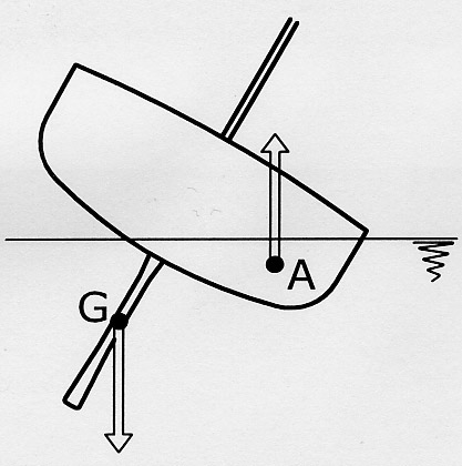
Capsizing effect of a sailing keel
A structural keel is a large beam around which the hull of a ship is built. The keel runs in the middle of the ship, from the bow to the stern, and serves as the foundation or spine of the structure, providing the major source of structural strength of the hull. The keel is generally the first part of a ship’s hull to be constructed, and laying the keel, or placing the keel in the cradle in which the ship will be built, is often a momentous event in a ship’s construction — so much so that the event is often marked with a ceremony, and the term lay the keel has entered the language as a phrase meaning the beginning of any significant undertaking. Modern ships are now largely built in a series of pre-fabricated, complete hull sections rather than being built around a single keel, so the start of the shipbuilding process is now considered to be when the first sheet of steel is cut.
The keel contributes substantially to the longitudinal strength and effectively local loading caused when docking the ship. The most common type of keel is the “flat plate keel”, and this is fitted in the majority of ocean-going ships and other vessels. A form of keel found on smaller vessels is the “bar keel”, which may be fitted in trawlers, tugs, and smaller ferries. Where grounding is possible, this type of keel is suitable with its massive scantlings, but there is always a problem of the increased draft with no additional cargo capacity. If a double bottom is fitted, the keel is almost inevitably of the flat plate type, bar keels often being associated with open floors, where the plate keel may also be fitted.
Duct keels are provided in the bottom of some vessels. These run from the forward engine room bulkhead to the collision bulkhead and are utilized to carry the double bottom piping. The piping is then accessible when cargo is loaded.
If a ship suffers severe structural stress — classically during a shipwreck when running aground in a heavy sea — it is possible for the keel to break or be strained to the extent that it loses structural integrity. In this case the ship is commonly said to have “broken its back”. Such a failure means that the entire structure of the ship and its machinery has been compromised and repairing such damage would require virtually re-building the ship from the ground up. A ship that has broken its back is almost certainly unsalvagable and subsequently written off by its insurers.
_oOo_
Hull (watercraft)
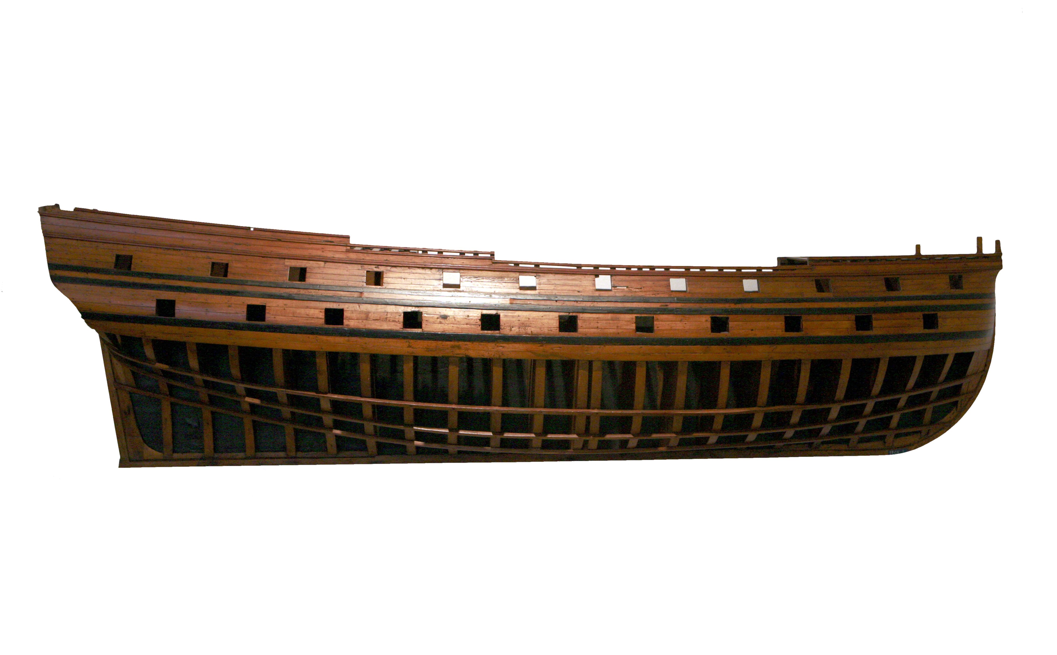
Half-hull of the 46-gun ship of the line Tigre, build from 1724 in Toulon after plans by Blaise Coulomb
*
A hull is the watertight body of a ship or boat. Above the hull is the superstructure and/or deckhouse, where present. The line where the hull meets the water surface is called the waterline.
The structure of the hull varies depending on the vessel type. In a typical modern steel ship, the structure consists of watertight and non-tight decks, major transverse and longitudinal members called watertight (and also sometimes non-tight) bulkheads, intermediate members such as girders, stringers and webs, and minor members called ordinary transverse frames, frames, or longitudinals, depending on the structural arrangement. The uppermost continuous deck may be called the “upper deck,” “weather deck,” “spar deck,” “main deck” or simply “deck.” The particular name given depends on the context—the type of ship or boat, the arrangement, or even the area where it sails. Not all hulls are decked (for instance a dinghy).
In a typical wooden sailboat, the hull is constructed of wooden planking, supported by transverse frames (often referred to as ribs) and bulkheads, which are further tied together by longitudinal stringers or ceiling. Often but not always there is a centerline longitudinal member called a keel. In fiberglass or composite hulls, the structure may resemble wooden or steel vessels to some extent, or be of a monocoque arrangement. In many cases, composite hulls are built by sandwiching thin fiber-reinforced skins over a lightweight but reasonably rigid core of foam, balsa wood, impregnated paper honeycomb or other material.

Hull Form”
***
Terms
Bow is the frontmost part of the hull
Stern is the rear-most part of the hull
Port is the left side of the boat when facing the Bow
Starboard is the right side of the boat when facing the Bow
Waterline is an imaginary line circumscribing the hull that matches the surface of the water when the hull is not moving.
Midships is the midpoint of the LWL (see below). It is half-way from the forwardmost point on the waterline to the rear-most point on the waterline.
Baseline an imaginary reference line used to measure vertical distances from. It is usually located at the bottom of the hull.
***

Principal hull measurements
*

“LWL & LOA”
*

“Beam, draft & Depth”
*
Hull forms are defined as follows:
-
- Block Measures that define the principal dimensions. They are:
-
- Length overall (LOA) is the extreme length from one end to the other.
- Length at the waterline (LWL) is the length from the forwardmost point of the waterline measured in profile to the stern-most point of the waterline.
- Length Between Perpendiculars (LBP or LPP) is the length of the summer load waterline from the stern post to the point where it crosses the stem. (see also p/p)
- Beam or breadth (B) is the width of the hull. (ex: BWL is the maximum beam at the waterline)
- Depth or moulded depth (D) is the vertical distance measured from the top of the keel to the underside of the upper deck at side.[2]
- Draft (d) or (T) is the vertical distance from the bottom of the hull to the waterline.
- Freeboard (FB) is the difference between Depth and draft.
- Form Derivatives that are calculated from the shape and the Block Measures. They are:
-
- Volume (V or ∇) is the volume of water displaced by the hull.
- Displacement (Δ) is the weight of water equivalent to the immersed volume of the hull.
- Longitudinal Centre of Buoyancy (LCB) is the longitudinal distance from a point of reference (often Midships) to the centre of the displaced volume of water when the hull is not moving. Note that the Longitudinal Centre of Gravity or centre of the weight of the vessel must align with the LCB when the hull is in equilibrium.
- Vertical Centre of Buoyancy (VCB) is the vertical distance from a point of reference (often the Baseline) to the centre of the displaced volume of water when the hull is not moving.
- Longitudinal Centre of Floatation (LCF) is the longitudinal distance from a point of reference (often Midships) to the centre of the area of waterplane when the hull is not moving. This can be visualized as being the area defined by the water’s surface and the hull.
-
- Coefficients[3] help compare hull forms as well:
-
- 1) Block Coefficient (Cb) is the volume (V) divided by the LWL x BWL x T. If you draw a box around the submerged part of the ship, it is the ratio of the box volume occupied by the ship. It gives a sense of how much of the block defined by the Lpp, beam (B) & draft (T) is filled by the hull. Full forms such as oil tankers will have a high Cb where fine shapes such as sailboats will have a low Cb.
- 1) Block Coefficient (Cb) is the volume (V) divided by the LWL x BWL x T. If you draw a box around the submerged part of the ship, it is the ratio of the box volume occupied by the ship. It gives a sense of how much of the block defined by the Lpp, beam (B) & draft (T) is filled by the hull. Full forms such as oil tankers will have a high Cb where fine shapes such as sailboats will have a low Cb.

-
- 2) Midship Coefficient (Cm or Cx) is the cross-sectional area (Ax) of the slice at Midships (or at the largest section for Cx) divided by beam x draft. It displays the ratio of the largest underwater section of the hull to a rectangle of the same overall width and depth as the underwater section of the hull. This defines the fullness of the underbody. A low Cm indicates a cut-away mid-section and a high Cm indicates a boxy section shape. Sailboats have a cut-away mid-section with low Cx whereas cargo vessels have a boxy section with high Cx to help increase the Cb.
- 2) Midship Coefficient (Cm or Cx) is the cross-sectional area (Ax) of the slice at Midships (or at the largest section for Cx) divided by beam x draft. It displays the ratio of the largest underwater section of the hull to a rectangle of the same overall width and depth as the underwater section of the hull. This defines the fullness of the underbody. A low Cm indicates a cut-away mid-section and a high Cm indicates a boxy section shape. Sailboats have a cut-away mid-section with low Cx whereas cargo vessels have a boxy section with high Cx to help increase the Cb.

-
- 3) Prismatic Coefficient (Cp) is the volume (V) divided by Lpp x Ax. It displays the ratio of the immersed volume of the hull to a volume of a prism with equal length to the ship and cross-sectional area equal to the largest underwater section of the hull (midship section). This is used to evaluate the distribution of the volume of the underbody. A low or fine Cp indicates a full mid-section and fine ends, a high or full Cp indicates a boat with fuller ends. Planing hulls and other highspeed hulls tend towards a higher Cp. Efficient displacement hulls travelling at a low Froude number will tend to have a low Cp.
- 3) Prismatic Coefficient (Cp) is the volume (V) divided by Lpp x Ax. It displays the ratio of the immersed volume of the hull to a volume of a prism with equal length to the ship and cross-sectional area equal to the largest underwater section of the hull (midship section). This is used to evaluate the distribution of the volume of the underbody. A low or fine Cp indicates a full mid-section and fine ends, a high or full Cp indicates a boat with fuller ends. Planing hulls and other highspeed hulls tend towards a higher Cp. Efficient displacement hulls travelling at a low Froude number will tend to have a low Cp.

-
-
- 4) Waterplane Coefficient (Cw) is the waterplane area divided by Lpp x B. The waterplane coefficient expresses the fullness of the waterplane, or the ratio of the waterplane area to a rectangle of the same length and width. A low Cw figure indicates fine ends and a high Cw figure indicates fuller ends. High Cw improves stability as well as handling behavior in rough conditions.

-
-
- Note:
- Note:

